The Mold Base with 3 plates has 3 cavity plates that allow more than 30 different sizes, from 150x150mm to 400x600m and with thickness going from 22 to 146mm.
Following every international regulation of coordinates and dimensions, Polimold guarantees the quality and safety of the 3 plates Mold base, offering a great product that will produce tools to make your business grow.
Plate’s Finishing
Every plate of the Standard Polimold Mold Base is finished by rotary ground machine process (thickness tolerance of +0,15mm/ +0,30mm). According to each project, there is also the option TO HAVE ALL PLATES FINISHED BY TANGENTIAL GRINDING (thickness tolerance of +0,05mm/ +0,15mm).
Supply Conditions
The molds of the series over 50-80 can be supplied with the guide pin diameter (D2) 60,00mm or 70,00mm, since the assembly coordinates are informed.
On the Polimolds over 50.50 the ejector set can be optionally provided with 6 guides, since the coordinates are informed.
The cavity plates with thickness equal or superior to 156mm has hole adjusts and components of 2/3 of their height.
The Polimolds with size between 15.15 and 20.20 can be provided with 4 columns on the ejector set, since the coordinates are sent by the client.
On assemblies 4,5 and 6 the return pins are included on the package.
The new Polimolds are supplied with a smaller diameter column on the edge replacing the offset guide pin.
Bolt Holes
The BOLTS are necessary to plates over 120kg/ or area over 500 x 500mm. They are centered on the thickness of the plate, except when the dimension “Z” is informed. On the 3 and 4 types it is required to inform the “A” measure.
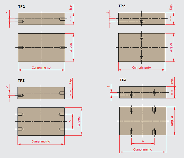
Subtitle:
Esp. = = Plates’s thickness
A = Distance between the bolt center
Z = offset distance from the center of Esp
To choose your Mold Base, please follow the steps below to determine the configuration according to your needs:
-
Step 2 – Choose the kind of mold +
The type of mold determines the right way to clamp it, and this choice can interfere on the width of the bottom and top clamp plates:
Type 3 Mold: Mold Base provided with clamp slot, on the superior cavity plate and also on rails.
Type 6 Mold: the clamp plates are supplied with the width larger than the width of the mold, to make it possible to allocate it on the injection machine.
-
Step 3 – Choose the thickness of the cavity plates +
The thickness of the cavity plates are related to the height of the product, cooling, insert of sliders, among other features. The sub-series is the ID of the thickness of the plates P1, P2 and P3 and their values are described on the “Sub-Serie” section ON our catalogue.
Click here and check all the available sub-series
-
Step 4 – Choose the kind of steel for the mold +
The steel used on the molds of Polimold were created for different applications. the plates that are part of structure are designed with steel SAE 1045 and the cavity parts can be made of steel sae 1045 or P20.Steel 1
It is the steel SAE1045 (DIN 1.1730). it has an average amount of carbon, easy usability and it is recommended for molds with pockets and inserts.Steel 3
It is the steel P20, recommended for cavity’s machining directly on the plates. Provided with HARDNESS from 28 to 34 HRC, it has excellent machining and allows great polishing, increasing the lifetime of the mold. Only the p1 and p2 plates will be made with P20 Steel, the others will be made of SAE 1045. -
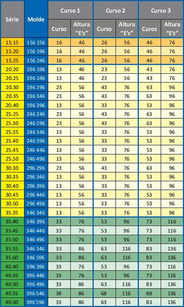
Step 5 – Choose the stroke of the mold. +
The Mold Bases from Polimold has 3 standard ejection strokes for each mold series. This stroke must be determined according to the necessary height to extract the product.Click Here to check all the available strokes.
-
Step 6 – Choose the type of assembly for the mold. +
There are 6 assembly options. They determine the inclusion of the extractor’s guides and the return pins.
TYPE OF ASSEMBLY DESCRIPTION IMAGE Assembly 1 Guide pin on p2 and bushings on p1 and pf 
Assembly 2 Guide pin on p2 and bushings on p1 and pf + ejector pin guides coming from bcp 
Assembly 3 Guide pin on p2 and bushings on p1 and pf + ejector pin guides coming from sp 
Assembly 4 Guide pin on p2 and bushings on p1 and pf + ejector pin guides coming from bcp + return pins 
Assembly 5 Guide pin on p2 and bushings on p1 and pf + ejector pin guides coming from sp + return pins. 
Assembly 6 Guide pin on p2 and bushings on p1 and pf + return pins. 
-
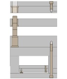
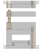
Step 7 – choose the guide style of the mold
Step 7 – choose the guide style of the mold
Polimold has 3 guide styles, please pick the more adequate to your project.
COLUMN DESCRIPTION IMAGE A Guide on cavity plates P1, PF and P2. 
B Partial guide of the mold with precise alignment between the cavity plates P1 and P2 and on support and top clamp plate 
C Complete guide with safe and precise alignment on all Polimold plates. 
-
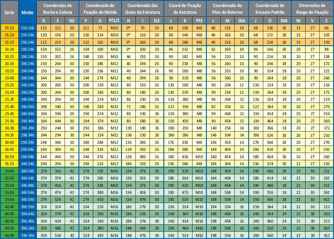
See the assembly drawing and view of the Porta Molde plan: +
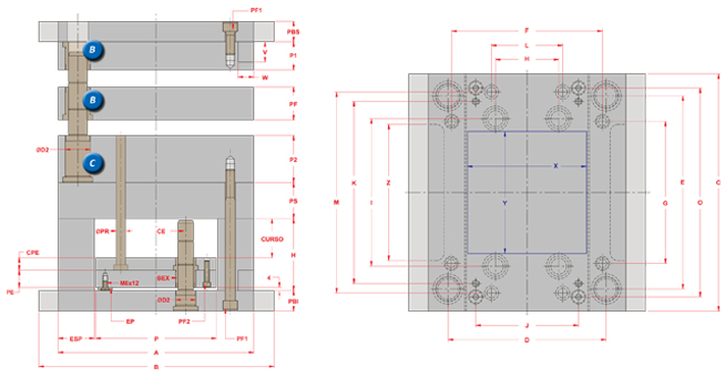
Click here and see the coordinates of the Porta Molde 3 plates.
- 1


